RetroBand is the second result of Arduino Wearable Project that is supported by open source. I think this shouldn’t be called a ‘smart band’ since it has only simple features. Actually, it’s rather to be called an “Activity Tracker”… But the term ‘smart band’ is more familiar to me, so I just call it a smart band. The important thing of smart bands is they are connected with mobile devices by Bluetooth and track the daily routine of users.
RetroBand that is implemented by Arduino has only one feature, which is collecting data by using accelerometer and sending them to a mobile device. Then the mobile device calculates the calories and steps by using the data. The feature is simple, and that means the structure of this device is way simpler than RetroWatch, so it’s very easy to make it in your own taste.
The android app check steps using collected data provided from RetroBand Arduino. The algorithm of the app is not that complicated. If you have much experience to this area, you can replace it with your own algorithm. The app saves the calorie data, so you can see the progress it in a monthly/daily/hourly graph form.
FYI, RetroBand Arduino cannot save the data itself since the shortage of its memory capacity. That is, it only works when it’s connected with a mobile device, which means you cannot collect the data with RetroBand Arduino only. I think this problem will be fixed when Arduino gets improved.
1. Mechanism
RetroBand consists of an Arduino part and an Android app.
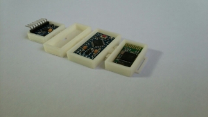
The Arduino has 4 main parts – Arduino board, accelerometer(MPU-6050), Bluetooth module(HC-06), lithum-polymer battery(charge board is optional).
The Android app contains of 4 parts – Android UI, Bluetooth manager, Algorithm section, background service.
If Arduino powers on and the pairing process with RetroBand app is done, the board check the accelerometer data 20 times in every 1 second. And it transfer the data to the mobile device once a second. The accelerometer measures x axis / y axis / z axis values, so the band sends 60 values(20 times x 3 axis) of data to the device.
The Android app receives the data during two seconds and finds out an interval that user’s movement increase dramatically. The number of user’s movement increase is user’s a step count. The app calculate burned calories based on user’s weight and steps, and accumulates data monthly, daily and hourly.
2 Preparation
If you want to buy parts which I used, refer to below links.
- Arduino Pro mini 3.3v – Ebay link
- Accel+Gyro sensor (MPU-6050) – Ebay link
- Bluetooth (HC-06) – Ebay link
- USB to UART converter (FTDI) – Ebay link
2-1 For Band(Hardware)
2-1-1 Arduino

I used the same Arduino board as RetroWatch, which is Arduino Pro Mini 3.3v(ATmega328). I chose this board because it works well with 3.7v lithium-polymer battery and its size, but if you don’t mind the size of the module and the battery or you just make the band as a test, you can use Arduino Nano board(it’s easy to implement and test).
Arduino Pro Mini runs at 8MHz and a 5v version at 16MHz, but 8MHz is enough. Overall, all you need to prepare are Arduino Pro Mini 3.3v and USB to UART(FTDI) module.
2-1-2. Bluetooth
Most common bluetooth modules that you can get are HC-06 main module and the one with interface base board. The latter one has a reset button, the status LED, and it supports both operation voltage(3,3v/5v), so this one is more convenient but the size is rather big, the LED, which is not quite necessary drains the battery. So I used a HC-06 without the interface board.
http://www.aliexpress.com/wholesale?SearchText=hc-06&catId=&initiative_id=SB_20140812220932

2-1-3. Accelerometer
I used the MPU-6050(6 DOF) accel + gyro sensor module. If you have other accel sensor you can replace it with yours. In this case, some of source code must be modified.
http://www.aliexpress.com/wholesale?SearchText=mpu+6050&catId=&initiative_id=SB_20140812220747

2-1-4. Battery
I use LiPo(Lithum-Polymer) battery in this project. 1-cell LiPo battery flows out current in 3.7v, which works perfectly with Arduino Pro mini, and there are many kind of batteries in terms of the size and the capacity. The choice is yours. Under 100mAh one is small, but it doesn’t guarantee stable power, and if it’s too low, you can’t even boot the system. I recommend the battery with protection circuit(overcharging, over-discharging safe), and it’s better if it has a removable socket.

For the convenience you can add LiPo charger module in below link. It supports charging with USB and power out pins for Arduino.
http://www.aliexpress.com/snapshot/6085015595.html
2-1-5. Etc.
You need wires, soldering iron, power on/off switch and a batter jack. It would be helpful for you to prepare the assembly manual.
2-2. For Android
The Android app for RetroBand is compatible with over Android 4.0
If you are using under Android 4.0 version or an iPhone…sorry, I don’t have any iOS devices and Mac, so I couldn’t make it.
3. Assembly
This is a picture that shows every module is assembled except the battery. FTDI will provide the power to the module for now, so the battery is unnecessary.

3-1. Connecting Arduino-Bluetooth module
If you want to know how to connect Arduino-Bluetooth module and test, click here. You just connect VCC, GND, TXD, RXD pin as the module in the instruction (VCC->3.3v, GND->GND, TX->D2, RX->D3). The Bluetooth module wouldn’t work well if it touches to other conducting objects or antennas, so be careful. You need to solder the module very delicately if you are using the module without an interface board. Once the module works okay after soldering, you need to fix it by a glue gun.

3-2. Connecting Arduino-Accelerometer(MPU-6050)
An accelerometer module uses I2C interface. If you need an explanation about I2C interface, click here. You don’t need to know about I2C interface in detail. The only thing that you need to know is the module gets the power through VCC(+), GND(-) pins and transfer the data through SCL and SDA pins.
3-3. Connecting Arduino – USB to UART module
In order to upload source codes by USB, you need to connect Arduino with USB – UART converting module(FTDI). If you need more information, click [here].
Caution !! : The way of connecting or usage can be different from this instruction. It depends on the USB to UART modules or their chipset. So you’d better check before you buy.
3-4. Connecting Arduino – battery
It’s very simple to supply the power. Just connect (+) -> RAW with (-) -> GND. But if you care about recharging, you can use a Li-Po recharging module. In this case, you should connect (+) and (-) connectors on the battery with B+,B- on the recharging module, and out+, out- on the module should be connected with RAW, GND on the Arduino board respectively.

3-5. Checking Connection
If you’ve got through all these process, it should be as below. You should connect each part except the battery. The power is supplied from FTDI module, so you shouldn’t connect the battery until source code upload and test are done. Every test finishes, disconnect FTDI module and connect the battery(or with Li-Po recharging module).

4. Arduino source code for band
You can download Sketch(Arduino source code for band) on Github. Go to the link below.
https://github.com/godstale/retroband
4-1. Arduino source compile
You need 3 libraries in order to compile Arduino source code for band.
math.h / Wire.h / SoftwareSerial.h
math.h is used to use functions for calculation, Wire.h is used to communicate with the accelerometer module in I2C, and SoftwareSerial.h is used to communicate with the Bluetooth module in Serial. I assume that most of recent Arduino IDE would support the libraries.
Click compile button on Arduino IDE. If you see ‘OK’, then you can proceed the next.
4-2. Uploading Arduino source
You need to upload Arduino source on Arduino board after the compile is done. Before you upload it, select board type ‘Arduino Pro mini 3.3v(ATmega328)’. And you should press reset button manually when you upload the source on Arduino Pro mini. If the process has failed, you can see this message :
arvdud: stk500_getsync():not in sync: resp=0x00
The reasons why this message appears are usually these:
1. The board type that you choose on Arduino IDE and the actual board is different.
2. The connection between TX, RX pins is wrong
3. Serial pins which are allocated as TX,RX are not used as they should be.
4. Bootloader on the board is malfunctioning
5. User doesn’t reset properly if they use a USB module that doesn’t support the auto reset feature.
Case 1, you should select a proper board type in [tools > board] on Arduino IDE, and case 2, you should check whether TX, RX pins are connected properly. If the connection is the same as case 3, disconnect D0 and D1 pin connection.
In case of 5, you should press the reset button. If you press the upload button on Arduino IDE, check the message appeared below the IDE. There’s a moment that it changes ‘Compiling’ to ‘Uploading’. You should press the button at that moment. If you see TX/RX LED on the USB module flickering, then the upload process is in progress.
Rarely, you can face the case 4. In that case, you should use an UNO board that is possible to upload the source to burn a bootloader on the malfunctioned board. The solution is way too long to describe and it’s out of our purpose, check the link below if you want to fix the problem.
https://forum.sparkfun.com/viewtopic.php?f=32&t=27960
http://arduino.cc/en/Tutorial/ArduinoISP/
4-3. Debugging
You need to verify every module connects each other and works okay.
First, you should run [Serial Monitor] on Arduino IDE to check if the accelerometer works fine(run the program when LED on the board is on after uploading Arduino sorce). Since the source code has a debug code as below, it should print out the values that are transferred from Arduino board if the connection is okay. If it doesn’t, there’s a problem in the connection with the accelerometer(you can delete the debug code once you finish to check).
  // Print the raw acceleration values
  Serial.print(F("accel x,y,z: "));
  Serial.print(accel_t_gyro.value.x_accel, DEC);
  Serial.print(F(", "));
  Serial.print(accel_t_gyro.value.y_accel, DEC);
  Serial.print(F(", "));
  Serial.print(accel_t_gyro.value.z_accel, DEC);
  Serial.print(F(", at "));
  Serial.print(iAccelIndex);
  Serial.println(F(""));
Now, you should check the Bluetooth. It would be found perfectly if VCC, GCN pins are connected properly when the mobile device starts scanning. If you don’t see HC-06 module on the found device list, check the power pin connection.
If you’ve done up to this part, it’s time to check the app.
# : If there’s nothing wrong with pairing process but the app doesn’t receive the data properly, there might be a problem in the connection of TX / RX pins. That is, the data don’t transfer from Arduino to Bluetooth module well.
5. Installing and Running the app
It’s very huge to explain how to compile Android source code and modify it, so I won’t cover it. But you can easily download the whole source code of the RetroBand Android source code on GitHub, and you may modify and distribute it. Just make sure that you preserve the copyright statement. You can find the source code of the app in [RetroBand_Android\RetroBand] folder
I distributed my app on PlayStore, so you can install it there(search ‘RetroBand’).
Over Android v.4.0 : https://play.google.com/store/apps/details?id=com.hardcopy.retroband
If you install the app, run it and pair the mobile device with RetroBand to see the app successfully receives the data. The app has 3 tab menus.
- Timeline : It gathers cumulative burned calorie data every hour. You can check how many calories you have burned hourly / daily / monthly
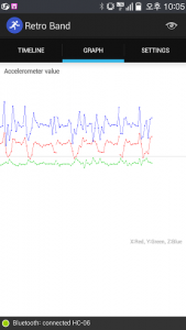
- Graph : It shows the graph that is drawn by the data sent from the accelerometer. You can see how 3-axis values alter.
- Settings : You can configure the app setting here, and input your weight here. Some features will be updated soon.


If you successfully test the app, connect Li-Po battery and finish the work.
The specification of RetroBand:
– Processor : ATmega328-3.3v(8MHz)
– 32KB Flash(2KB is shared for Bootloader), 2KB RAM, 1KB EEPROM
– Connected with Android exclusive app(supported over v.4.0).
– Calculating calories based on step count.
– Accumulating calorie data and displaying statistics in a monthly/daily/hourly data
– Real-time check of the change of the 3-axis values measured by accelerometer
– Open source
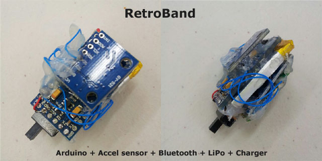
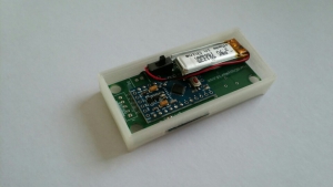
You can see the prototype in the picture below. It’s the combination of Arduino + accelerometer + Bluetooth module + recharging module + Li-Po battery + power switch. I plastered glue on it so it looks messy, but it worked pretty well.
6. Packaging
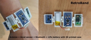
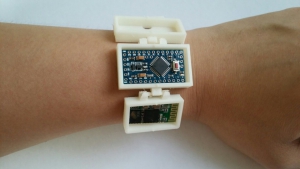
If you have a 3D printer, try to make your own case. What you are seeing in the picture below is the case that is made by a 3D printer, which embeds every module except a recharging module and is worn like a wrist band.
Prototype for test. (Arduino+Accel sensor+Bluetooth+LiPo Battery+Charger+Power Switch)

Arduino+Accel sensor+Bluetooth+LiPo Battery+Power Switch on custom PCB.

7. Epilog
RetroBand is my second project succeeded to ‘Making a SmartWatch(RetroWatch)’. My smart band is too simple to compare other activity tracking products, but a Bluetooth module and an accelerometer are the basic modules that can be used in any other projects. You can make variables by using the source that I used.
I hope this would be helpful to you and thanks to people who helped me for this project. I’ll post other project after I take a break and finish to make a document for this project.
2014. 08. 01. GodsTale
Arduino, Android source(GitHub) : https://github.com/godstale/retroband
RetroBand Android App(Google Play) : https://play.google.com/store/apps/details?id=com.hardcopy.retroband
Original DIY documents : https://www.hardcopyworld.com/?p=975 (English)
Homepage : HardCopyWorld
Special thanks to : Chang-Han Jeon(Translated docs in English), Wired Factory team(Il-Yong Park, Byung-Gyu Kim, KyungReol Ku, Sang-Won Lee, Kyung-Bu Jeong)

[…] Translated in English!! (by Chang-Han Jeon) […]
[…] Project homepage:?http://www.hardcopyworld.com/ngine/aduino/index.php/archives/975 […]
Works well, straight away after soldering! Very nice.
I wonder if you did any filtering (Kalman) in the android code. Did you?
Thanks for making this available.
No I used accel data only. And used the simple peak detection algorithm to detect walks.
[…] Opis projektu miernika aktywno?ci fizycznej w serwisie Hardcopyworld […]
Hi\
Thanks for your efford. I made one it works fine but in order to put it in a shape I need the case. I have my own 3d printer that is not a problem. Would you mind if you send me the drawing files?
Best wishes.
I’m sorry but 3D printed case in the picture is not my work.
Thanks for this DIY guide, it looks like something I want to get into. One question. You say “You need wires, soldering iron, power on/off switch and a batter jack. It would be helpful for you to prepare the assembly manual.” Do you have any links/suggestions for the missing parts, such as the on/off switch? Not sure what I should be looking for. This will be my first Arduino project.
you can easily find such modules from Adafruit.com or aliexpress.com. Search with module name like “switch”.
[…] Opis projektu miernika aktywności fizycznej w serwisie Hardcopyworld […]